Corvus 1F
Introduction
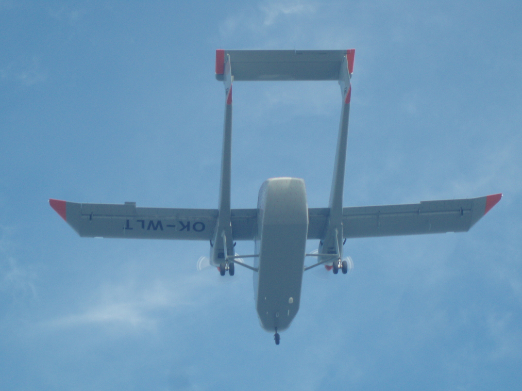
During year 2007 I improved the aerodynamic of an interesting aircraft.
The Corvus aircraft is under development for about 10 years and was facing the problem of having a ratio of
engine power to drag very small.
This is particularly critical for twin-engines aircraft with MTOW of more than 2722kg wishing to be
certified under FAR/CS-23, "normal category", because their ability to take-off at a given weight
is limited by the climb gradients as defined by the regulation:
- CS 23.67(b)(1)
The steady gradient of climb at an altitude of 122 m (400 ft) above the take-off surface must be measurably positive with –
(i) The critical engine in-operative and its propeller in the minimum drag position;
(ii) The remaining engine at take-off power;
(iii) The landing gear retracted;
(iv) The wing flaps in the take-off position(s); and
(v) A climb speed equal to that achieved at 15 m (50 ft) in the demonstration of CS 23.53.
- CS 23.67(b)(2)
The steady gradient of climb must not be less than 0·75% at an altitude of 457 m (1 500 ft)
above the take-off or landing surface, as appropriate with –
(i) The critical engine in-operative and its propeller in the minimum drag position;
(ii) The remaining engine at not more than maximum continuous power;
(iii) The landing gear retracted;
(iv) The wing flaps retracted; and
(v) A climb speed not less than 1·2 VS1.
- CS 23.77(b)
For normal, utility and aerobatic category each reciprocating engine-powered aeroplane of
more than 2 722 kg (6 000 lb) maximum weight and turbine engine-powered aeroplanes in the normal,
utility and aerobatic category, the steady gradient of climb must not be less than 2·5% with –
(1) Not more than the power or thrust that is available 8 seconds after initiation of movement
of the power controls from the minimum flight-idle position;
(2) The landing gear extended;
(3) The wing flaps in the landing position; and
(4) A climb speed equal to VREF, as defined in CS 23.73 (b).
Notes:
- Paragraph 23.53 defines the conditions for determining take-off distance.
- Paragraph 23.73 defines the approach speed Vref for final approach up to 50ft above the landing surface.
- For a given airport altitude and ambient temperature, the maximum weight at which an aircraft will be
allowed to operate must fulfill the 3 requirements.
- The limitations can be plot on a graph and are commonly named WAT curves (for Weight, Altitude, Temperature).
The Corvus was so badly designed that for an airfield at Sea-level, in ISA conditions, the take-off
weight had to be limited to 2800kg, which is quite low when compared to the MTOW of 3100kg.
Well designed airplanes are still able to take-off at their MTOW from hot-and-high airfields.
To cure I combined two methods: First I added wing-tips, then I decreased the base drag with vortex generators mounted on the rear part of the fuselage.
Wing tips
 For most of people (and sometimes even for managers in aircraft industry), Winglets is a magical thing
that solve all problems with performance, make the aircraft looking more sexy, and all for free. When comes
the time to design the winglets, usually a bunch of people without any aerodynamic knowledge try to feel
how it should looks like. All of them are persuaded that instead of spending days of laborious computation and fastidious analysis,
it's enough to repeat several times: Marcel Dassault said that a beautiful aircraft is always flying well,
my design looks fine so I am the cleverest man here. Usually at this point, you know you will spend half of your working
time just trying to prevent them against themselves.
For most of people (and sometimes even for managers in aircraft industry), Winglets is a magical thing
that solve all problems with performance, make the aircraft looking more sexy, and all for free. When comes
the time to design the winglets, usually a bunch of people without any aerodynamic knowledge try to feel
how it should looks like. All of them are persuaded that instead of spending days of laborious computation and fastidious analysis,
it's enough to repeat several times: Marcel Dassault said that a beautiful aircraft is always flying well,
my design looks fine so I am the cleverest man here. Usually at this point, you know you will spend half of your working
time just trying to prevent them against themselves.
From a technical point of view, the reality is not so poetic. In a very simplified form, the drag of a
subsonic aircraft can be broken into two main parts:
- Airframe drag: It's the drag generated by the airframe (or any body), because the ambient air, initially at rest,
must move to make space for the aircraft. It can be subdivided in more details, for example parasite drag when
talking about the drag due to rivets or nuts. Basically, the bigger the aircraft, the bigger its airframe drag.
- Drag due to lift. When moving through the air, the aircraft (and especially the
wings) deviates the air;i.e. the air will not came back to its initial position after the aircraft has moved on.
This creates a force on the air, and by reaction an equivalent one on the aircraft that lift it.
The energy required to do it is the so call induced drag and increase roughly as the square of the lift.
to be continued as soon as I will have some free time
Base drag
Trailing-edge
Videos
You can see videos taken by a guy from the company when I made flow visualization:
here
and
here